Profiting on waste heat
Recovering energy
Industries
Heat exchanger designs
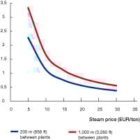
Payback analysis
Contact Us
Saving fuel
Generating electricity and mechanical work
Selling heat and electricity
Reducing cooling needs
Reducing utility investments
Increasing production
Reducing greenhouse gas emissions
Transforming energy
Preheating in interchangers
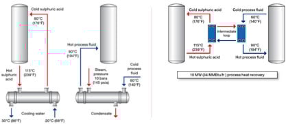
Direct process heat integration
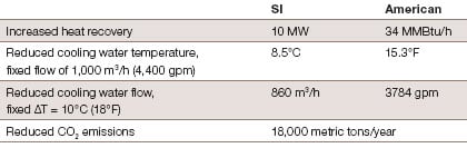
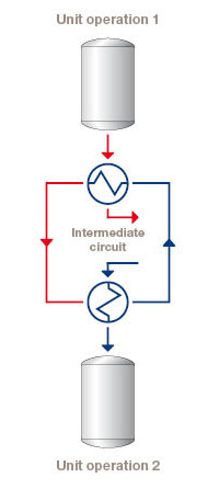
Indirect process heat integration
Increased number of effects in evaporation systems
Reduced fouling and maintenance
Reduced steam temperature
Generating steam from flue gases
Boosting compressor capacity
Reduced need for chilled water
Improved turbine performance